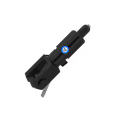
RG-8.0-ST-下颌
RG-8.0-ST-下颌
Product Code
SKU:393.009.005
低库存:剩余 2
无法加载取货服务可用情况
- 当空间有限时非常完美
- 多功能 M20 接头
- 经 TUV 测试和认可的产品
这款重型 TG8 黑色粉末涂层 TECNI 夹钳和柱塞附件可容纳 6 毫米至 8 毫米的电缆。该配件有一个可拆卸的销钉,非常适合悬挂大型物品以进行悬挂和展示 - 可根据要求提供其他颜色。
目录代码:393.009.005nbsp;
Applications & Advice
Applications & Advice
How to safely connect the grip slider to the wire rope:
1. First, loosen the lock nut mounted on the threaded nose protruding from the grip slider’s top end (nozzle) until the end of the thread is reached. Next, insert one end of the wire rope into the grip slider against the slight resistance of the spring-loaded nozzle.
2.The grip slider can now be slid along the wire rope. As soon as it is pulled in the opposite direction or loaded, the gripping mechanism will be automatically activated. If the gripping mechanism is not triggered as it should, please check whether the wire rope selected for use with the grip slider is appropriate (see table with working loads), or whether the grip slider is possibly defective (in order to check the grip slider prior to use, please refer to the “Safety Advice/Precautionary Statements” section, steps 1…7). ! In case of a suspected malfunction or defect, the grip slider should NOT be used !
3. Care should be taken that the wire rope, prior to the gripping action being triggered, is properly channelled through the grip slider so that it protrudes under load by at least L= 60mm (2.4 inch) from the coupling thread, coupling part or side exit (ZW) of the grip slider (Fig.2, 2a), depending on the model used. In addition, the angle α=5° max. between the wire rope and the vertical symmetry axis of the grip slider must not be exceeded at the point of exit of the cable from the nozzle. If the angle is larger, the lateral pressure exerted by the wire rope on the nozzle can cause damage to the nozzle or malfunction of the grip slider, thus possibly leading to an accidental release of the gripping mechanism.
4. After the grip slider has been adjusted to the required position on the wire rope by a gentle pulling action of the hand (in direction of load), the grip slider will begin to grip.
5. Once the grip slider has properly gripped the wire rope, tighten the lock nut by hand (without the use of tools!) until it comes to closely rest against the top end of the grip slider. The load can now be attached to the grip slider; the gripping force of the grip slider increases in proportion to the work load. Care should be taken to ensure that load attachment to the tensioned wire rope is performed slowly and gradually.
6. After proper attachment of the work load, re-tighten the lock nut further by hand (without the use of tools!) until it makes full-surface contact with the grip slider.
7. Pulse loading (shock loads) may cause the safe working load (working load limit) to be temporarily exceeded and may thus lead to damage of the wire rope and the grip slider. If any such pulse loading (shock load) has occurred, the load should be removed, and the wire rope, as well as the grip slider, should be checked for damage immediately.
If the grip slider or the load is to be relocated on the wire rope (i.e. on a new position), please proceed in reverse order:
1. Loosen the lock nut, remove the suspended load or secure it expertly to the grip slider to prevent accidental dropping of the load.
2. Manually press the lock nut, thus pushing the nozzle into the grip slider, and keep it in that position. The grip slider is now unlocked - means the gripping pressure is released. 3. You can now slide the grip slider to the selected position on the wire rope.
4. Release the lock nut once again; while you do so, the nozzle should move out from the grip slider and return by itself to its original position outside the grip slider.
5. For re-applying the load, please proceed once again as described from step 4 of the “How to safely connect the grip slider to the wire rope” section.
Technical Info
Technical Info
1. Reutlinger grip slider are only approved for indoor use at temperatures between –20…+50°C.
2. Use of the grip sliders in swimming facilities (with a chloric atmosphere) or in any other corrosion-promoting environments (sea water areas or locations with high salt concentration in the atmosphere) is not permitted.
3. Grip slider are not permitted for continuous dynamic scenic movements of mechanical equipment (moving loads and persons over persons in the danger zone is strictly prohibited). During the procedure and operation of the electric chain hoists in set-up mode (lifting and lowering of the load during assembly and dismantling), no persons may be present in the danger zone. All dynamic forces that act or can act on the wire rope hoist during assembly and dismantling must be taken into account on a case-by-case basis when determining the maximum working load to be applied. The specified working load limit (WLL) must NOT be exceeded AT ANY TIME.
4. The casing of the grip slider must be impossible to open and must never be opened. Permanently fixed original parts should not removed.
5. Before the grip slider is used, its nozzle (i.e. the threaded nose protruding from the cable holder’s top-end) must be able to be pushed inside with ease against the noticeable pressure of the spring, and it should move out again by itself and return to its original position outside the grip slider when it is released.
6. The pass-through channel of the nozzle must be free of foreign particles so that proper functioning of the grip slider is ensured.
7. When looking through the nozzle, part of the circumference of six balls protruding into the nozzle’s pass-through channel must be visible (Fig.1). The lighter, central gap formed by the configuration of the six balls is to form a hexagon in the pass-through channel, similar to a star with six points. If the six balls are not visible in the grip slider as described above, the grip slider should not be used. Contact the Quality department of Reutlinger GmbH.
8. The surface of the wire rope to be threaded into the grip slider must be properly closed (i.e. sealed by tinning, welding, shrink-sleeving,…) so that an unravelling of the wire rope and thus injury to the user from projecting wires or strands is prevented. If the wire rope needs to be shortened, its ends must be once again permanently sealed after the trimming is complete.
9. For safe operation and full load capacity (i.e. up to the working load limit) of the grip slider, the wire ropes must be entirely undamaged and free of dirt or other contamination.
10. Wire ropes and wires must not be pulled over edges (e.g. in case of models with side cable exit)!
11. The deflection angle of the wire rope from the vertical symmetry axis of the grip slider must not exceed α=5° (Fig.2, 2a).
12. The nozzle of the grip slider must under no circumstances be loaded (e.g. it must not be exposed to buckling or compressive stress etc.). It must remain accessible at all times.
13. The grip slider must be used in pairs as a minimum, i.e. the object to be suspended must be held by a minimum of two wire ropes in order to prevent rotation of the grip slider upon ist own axis on the wire rope.
14. After overload, above the indicated safe working load (working load limit), grip slider should not be used again!
15. Wire ropes and grip slider should not be damaged ! „Critical Damage” includes (but is not limited to): Cracks, deformations and material loss such as may occur through impact, shock or severe friction/abrasion. Slight abrasion or deformation of the nozzle may indicate presence of damage inside the grip slider caused by, for example, an impact on the nozzle (e.g. by falling onto a hard surface). In case of any doubts or questions as to whether a particular Reutlinger grip slider exhibits uncritical traces of use or potentially critical damage, please contact Reutlinger GmbH to be on the safe side.
16. Do NOT use any tools when mounting the grip slider onto its respective mating counterpart or when tightening the lock nut (safety nut).
Dimensions
Dimensions
Video
Video